RAD Mod - External Battery
Ride All Day!
This is a tutorial for an ADVANCED MOD where an external battery is connected, bypassing the onboard battery pack.
This modification includes soldering, drilling, and harness building. Previous experience in these areas is recommended/required. Instructions for harness building and general fabricaton are NOT INCLUDED in this tutorial.
The overall concept is to set up a wiring harness to allow switching between the onboard battery and a larger external battery for greatly extended range and increased performance without using any additional converters or carrying any extra weight.
How it Works
For a little history of how and why, check out the pioneer of the external battery back here:
External Battery - https://www.youtube.com/watch?v=nQDdJWULxsY
External Battery pt2 - https://www.youtube.com/watch?v=8LCh98zPPyo
Pros and Cons
| Pros | Cons |
|---|---|
| Allows for customized range | Warranty is done done done |
| More cells in parallel exhibit lower voltage drop and can output more continuous power | Battery compartment must be opened |
| Can be implemented to correct issues with the stock BMS or the stock battery | Drilling/soldering required |
| Nothing hanging out of your charge port. Setup is more robust, less prone to accidental damage. | Loss of amp measuring and cell voltage (see BMS bypass note) |
| Preserves Original Battery | Loss of cell balancing |
| Onboard battery and external battery can be charged through chargeport. | |
| Switch back and forth between onboard battery and external battery for "naked riding" and long range cruising | |
| Bypassing BMS means no accidental shut-offs, regen warnings, and other BMS associated issues | |
| Compatible with all OW versions (different battery pack setups may be necessary for optimal results) | |
| No MPPT or other converters necessary, all onboard weight is pure range (unless carrying a charger) |
Parts List
This is meant to be a suggested parts list rather than a specific build of materials. Components can be replaced based on user requirements/preferences.
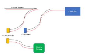
XT90S Connectors: These antispark connectors will precharge the controller instead of slamming it with the full 58v upon connection of the harness. This is recommended to prevent any damage to the control module. A separate precharge resistor circuit can be hooked up beforehand if alternate connectors are desired.
https://www.amazon.com/gp/product/B0732S5V85/ref=oh_aui_detailpage_o02_s00?ie=UTF8&psc=1
Adhesive Heat-shrink:
https://www.amazon.com/gp/product/B01N6EFUKR/ref=oh_aui_detailpage_o04_s00?ie=UTF8&psc=1
Grommet: Used to secure the wires travelling through the battery case
https://www.lowes.com/pd/Hillman-2-Pack-0-625-in-Rubber-Grommet/3013196
14AWG Wire (Black and Red)
EC3 Conncetors
Battery Pack
Battery Pack Spec Requirements
Similar to the CnR mod or the charging on the go setup, a battery pack must be sourced for this application. The goal here is to match the voltage of the existing battery.
In order to get the full advantage of the RAD mod, it is recommended to use a battery with more than one set of parallel cells. This shares the load between the cells and increases the overall performance (by reducing voltage drop).
Each parallel set of cells is roughly equivalent to 7-miles range, or similar to whatever range you were getting on the OW+
Options:
1) LiFePO4 (same chemistry as original battery) Nominal cell range 3.0-3.62v/cell or 48V Empty, 58V full.
Specs: 16s1p or greater.
2) Li-ion (18650 ebike style packs or pouch-style packs) Nominal cell range 3.6v-4.2v/cell or 50.4V Empty, 58.8V full.
Specs: 14s1p or greater
Conclusion: Allthough there are benefits to using the A123 LiFePO4 cells, it is the opinion of the tutorial creater that the Li-ion pack has a more favorable nominal pack voltage window (slightly better performance in most situations) and is ultimately similar in safety. The availability of Li-ion cells is also an advantage.
Nominal pack voltage window:
Where to put the Battery Pack
1) In a backpack. Similar to the CnR method, the battery can be padded and stored inside a backpack with the wiring harness hanging out. It is recommended to use some combination of bungees, magnets, or velcro to shorten up the cable while riding but allow for the connection to maintain when you are standing within 2ft of the board.
3) On-board. Wrap the battery in padding and attach to your fender in any variety of ways. This shortens the wire harness and gives you a completely backpack/hands free approach.
Battery Pack Sources:
https://em3ev.com/shop/50v-14s5p-rectangle-battery-pack/
14S, 5P - 40-45 mile range. $500 (power cells recommended but any 14S pack will work.)
Charging
Charging can be done in several ways.
1) External charger: There are a number of 14S chargers out there for the Ego battery packs and similar ebikes. YMMV with the charge rates and full voltage settings.
It is highly recommended to limit full voltage to 57v if no BMS or balancing solution is being used. Similarly, it is recommended not to fully discharge your battery if there is no LVC cutoff/alarm.
The highest quality, fully programmable charger is the Cycle Satiator http://www.ebikes.ca/product-info/cycle-satiator.html
Some ebike battery packs will come with a charger (2-3A typically). These work the same as the OW charger except a little slower.
2) Stock charger: Although extremely slow for charging a big pack, the stock charger can be used through the XLR charge port, as long as the battery is plugged in and the board is on.
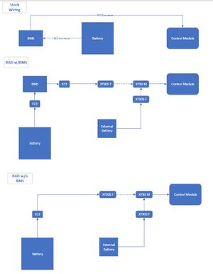
Wiring Diagram
Assembly
New Method:
- Open battery pack and disconnect onboard battery
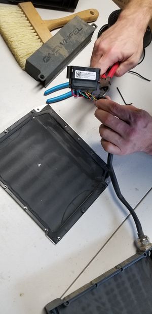
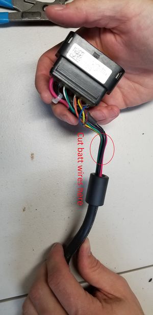
- Peel back the insulation on wire harness where it connects to the controller
- Cut battery + and - wires
- Splice in 12awg wire to harness side and to the controller side
- Run loop of wire (4 wires) to XT90 connectors
- Secure wires to frame in multiple places (zip ties or other methods)
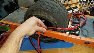
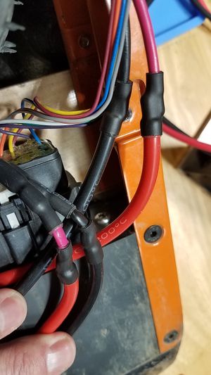
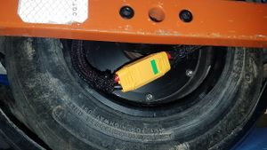
== Assembly Pictures ==
BMS Bypass
- The BMS bypass can be used in combination with the RAD mod or it can be used alone.
- The reasons for eliminating the BMS:
- BMS has failed or is inaccurately reading cell voltages and shutting off the board.
- Removes the ability for the BMS to cut power to the controller under any circumstances (good or bad.
- * Note: The controller will still shut off the board when the voltage drops too low (battery empty is ~48v). It is highly recommended to avoid this situation.
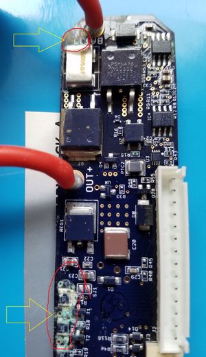
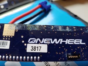
- Example of failed BMS due to corrosion of balance resistors. (incorrect voltage being read).

